Pressure Sensor Matrix

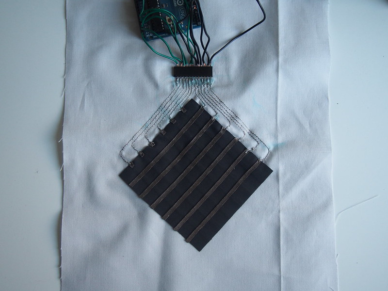
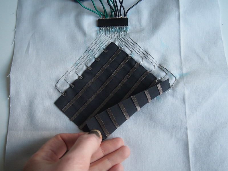
This pressure sensor matrix allows you to detect where pressure is being applied in a specific location. It is an adaptation of Kobakant’s pressure sensor matrix (design here, Arduino code here, and Processing code here).
Materials + Tools:
+ Stretchy Conductive Fabric from lessEMF
+ Eeontex Stretchy Fabric from Sparkfun
+ Karl Grimm Conductive Thread
+ Header pins
+ Fusible interfacing
+ Regular fabric
+ Fabric glue
+ Soldering Iron
+ Ruler
+ Scissors
+ Needle
Steps
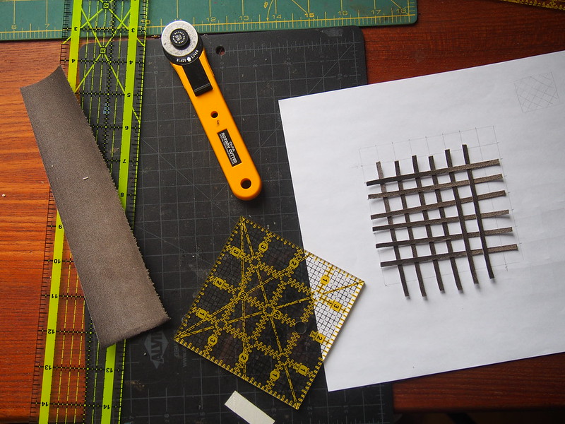
Draw out your 6×6 grid and determine what spacing you want. The space between the conductive rows and columns should depend on how you want someone to use it as an interface. If you want to read multiple points at once, put them closer together. If you want to read points discretely, you can place them farther apart. For my grid, I had about .5 inches of spacing and I got good point specific location readings. Draw the columns on one side of the Eeontex piezoresistive stretch fabric using a chalk pen and the rows on the other.
Iron stretch conductive fabric onto fusible interfacing. Fusible interfacing allows you to iron the conductive fabric onto any other fabric and it will adhere (i.e. no sewing required). Next, cut small strips (I cut them little less than .2 inches in width) of conductive fabric for your grid.
Iron on your conductive strips to the front and back of the Eeontex fabric using the chalk lines as a reference.
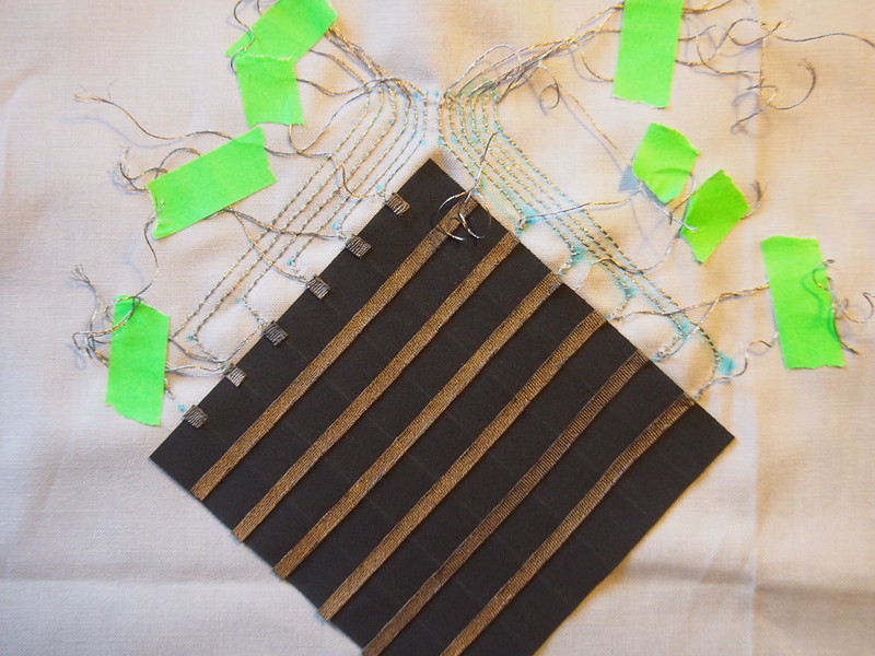
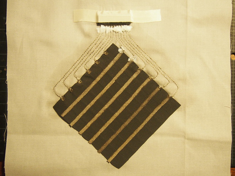
Next, grab 12 male or female header pins and mark there location on a separate piece of fabric that will house the sensor. Draw lines that connect each column and row up to the header pins, then machine or hand stitch the traces to connect to the header pins. Remember to leave at least 2-3 inches on either end of the trace so you can sew it to the sensor or solder it to the header pin. If you use a machine, remember to put the conductive thread in the bottom bobbin.
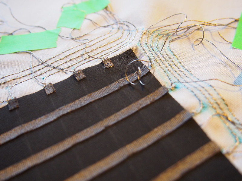
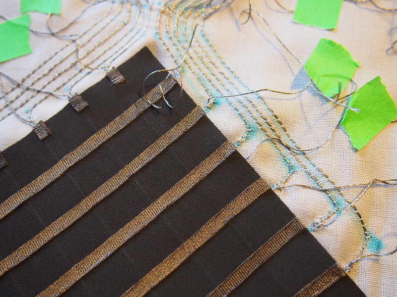
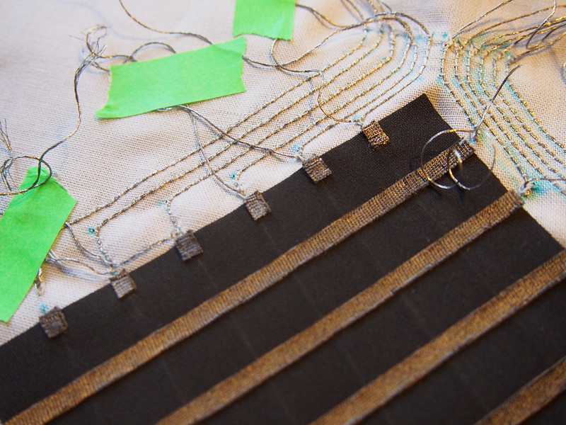
Sew each conductive thread trace to a row or column. Be sure to keep it clean and cut excess thread, then cover with hot glue, fabric glue, or a piece of tape.
Once you’re finished sewing the traces to the sensor, now it’s time to connect them to the header pins. Any excess thread should be on the back side so you have a clean, clear trace to solder to. Solder away and be sure no traces are touching! Once you’re done, put a healthy glob of fabric glue on them. Once it’s dry, trim all the excess thread from the back – remember: NO TRACES SHOULD BE TOUCHING!
Time to connect it to Arduino and Processing! Use the links to the code above.
