Stress Sensing Apron
I love a good excuse for a project.
Not only because I love making things, but I like designing experiences and if they have deadlines and an audience, even better. This project was specifically designed for me to wear at our Cooking with Hardware panel. After a few TeamBlinky conversations around personal data, bio-sensing, and storytelling, I began brainstorming a piece of DIY wearable technology that would reveal what I knew, but no one else can generally tell: my stress level during a round of public speaking. That’s right, I will be showing the audience whether or not I am feeling overly aroused during our talk.

When I place my hand in the pocket of the apron, my fingers will find two electrodes that act as a Galvanic Skin Response (GSR) sensor, which measures skin conductance. When you are physically or psychologically aroused, your sweat glands secret moisture, thereby increasing skin conductance. Here’s how the sensor works:
Two electrodes comprise the sensor: one is connected to power that sends current, while the other is connected to ground via a 200K Ohm resistor that measures difference. The GSR sensor we are constructing here is *very* simple, basically a variable resistor. Ideally, we would have constructed a more complex circuit using a low pass filter and better timing on the code, but I wanted an easy project and entry point for p comp noobs. Hence, it won’t be completely accurate and you might have some noise. For a more advanced version, check out Chris Kairalla’s documentation.
While I don’t have a terrible fear of public speaking, I definitely have overactive nerves. There are five LEDs on the apron. If I am at my tranquil baseline, the LEDs are lit. If I am feeling aroused, the LEDs begin to fade slowly to induce a state of calm. I actually anticipate this will be quite a liberating experience, and that the performative nature of the act will outweigh feelings of vulnerability stemming from such exposure. Bring on the talk.
Materials
Apron
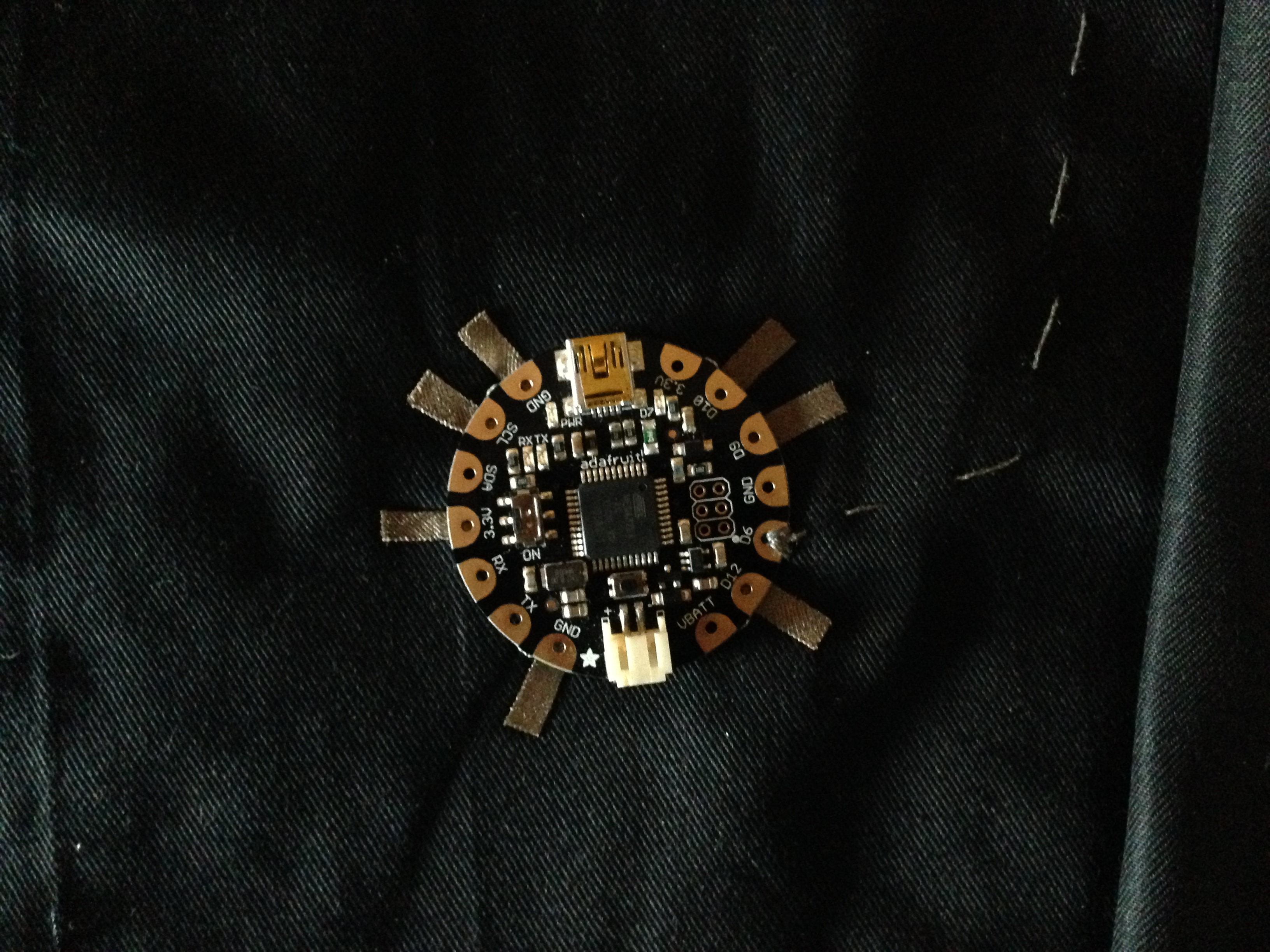
Adafruit Flora
LiPo Battery
LEDs (surface mount recommended)
Conductive Thread
Conductive Fabric
Fusible Interfacing
Embroidery Hoop (Size 6) (optional)
Needle (Embroidery needle recommended)
Hot Glue Gun
Iron
Small Needle Nose Pliers
Tracing Chalk/Paper
Step 1: Map and outline out your circuit
This is where you can get super creative with your project. I didn’t have a chalk pen, so I had to use tracing paper and a steady eye. Mark where your LEDs (I used 5, but you can use however many you want), sensors, and Flora will go.
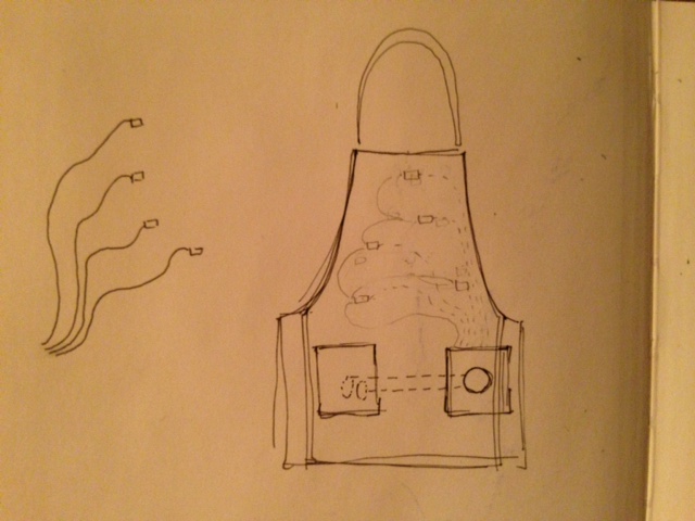
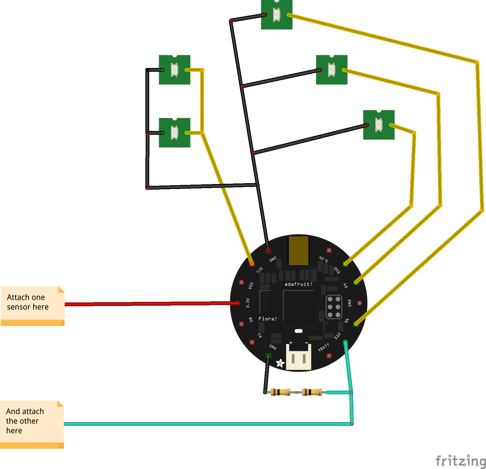
Here is what the basic circuit looks like:
Step 2: Fall in love with fusible interfacing
Because in projects like these, it is the best friend you will ever have. Fusible interfacing allows you to adhere two pieces of fabric together using heat. Adhere the non-paper side of the fusible interfacing to your conductive fabric, then peel off the paper and iron the other side to the apron. Let it sit for a sec before checking to make sure it is secure. It conducts more heat than regular fabric, so it takes more time to cool.
Step 3: Adhere LED pads
(Note: If you are using non-surface mount LEDS or sewable LEDs, no soldering is required. For regular LEDs, wrap each leg around needle nose pliers to create a hoop, then adjust the hoop for sewing. )
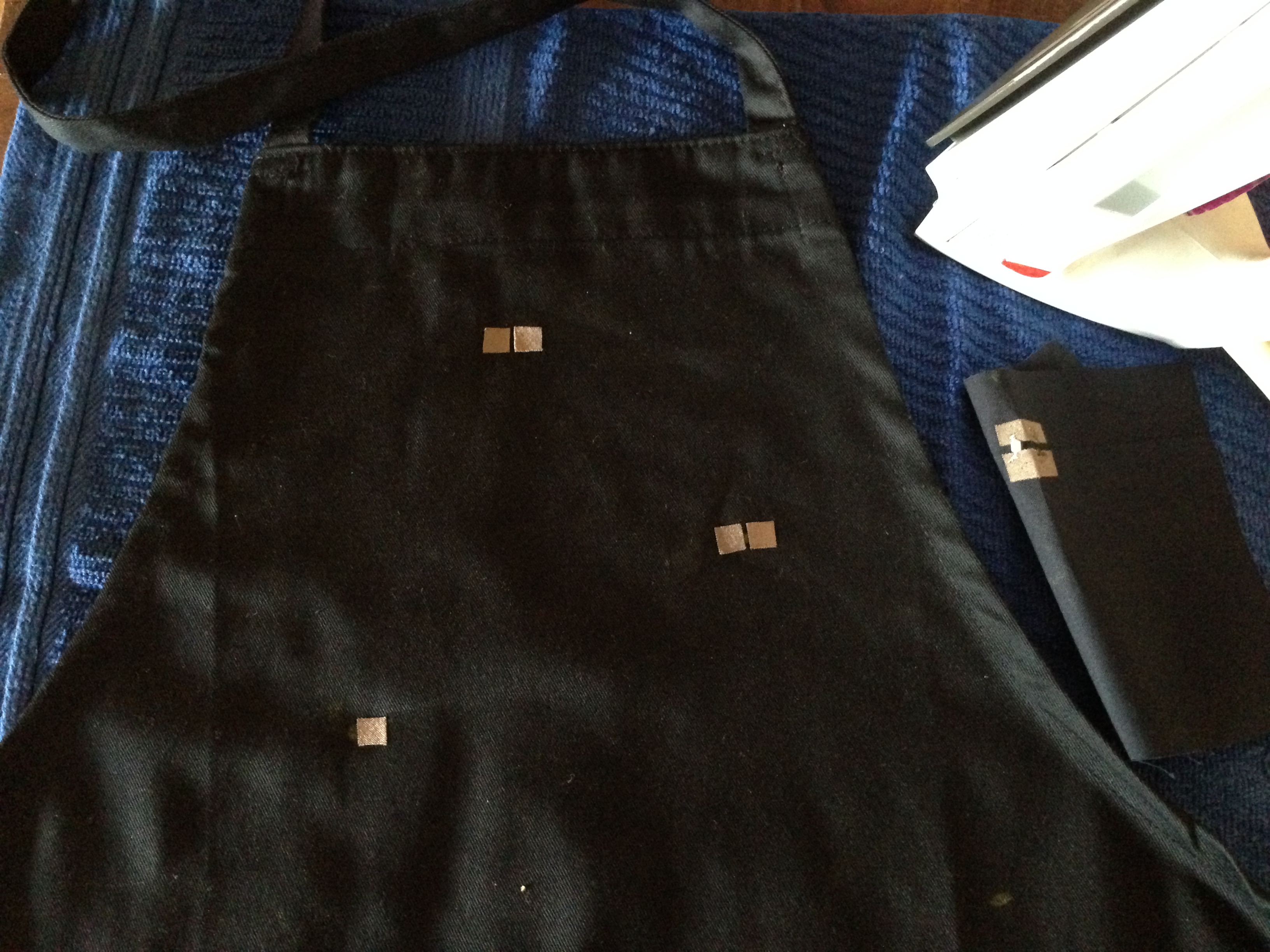
We are NOT adding the LEDs yet, just where they will go. Cut 1/4″ squares from the conductive fabric you just created above. Peel off the paper and place one according to your circuit. Adhere using an iron. Measure the space apart for the second pad based on your LED. Be sure they do not touch! Adhere using an iron.
Step 4: Adhere Flora pads
Measure strips from the conductive fabric fusible interfacing you created and adhere them under the pins you are using. (I used 3,6,9,10 for the LEDs and 11 for the sensor.)
Step 5: Sewing Traces, Part 1: Which stitch should I use?
Use a straight stitch- no backstitches – if you want to get fancy, reduce the amount of space between the LEDs and the Flora. In my experience suggest this for three main challenges I have combatted in the past:
- 1) Cost. Conductive thread is not as cheap as its cotton counterpart. We want to use it sparingly to a degree.
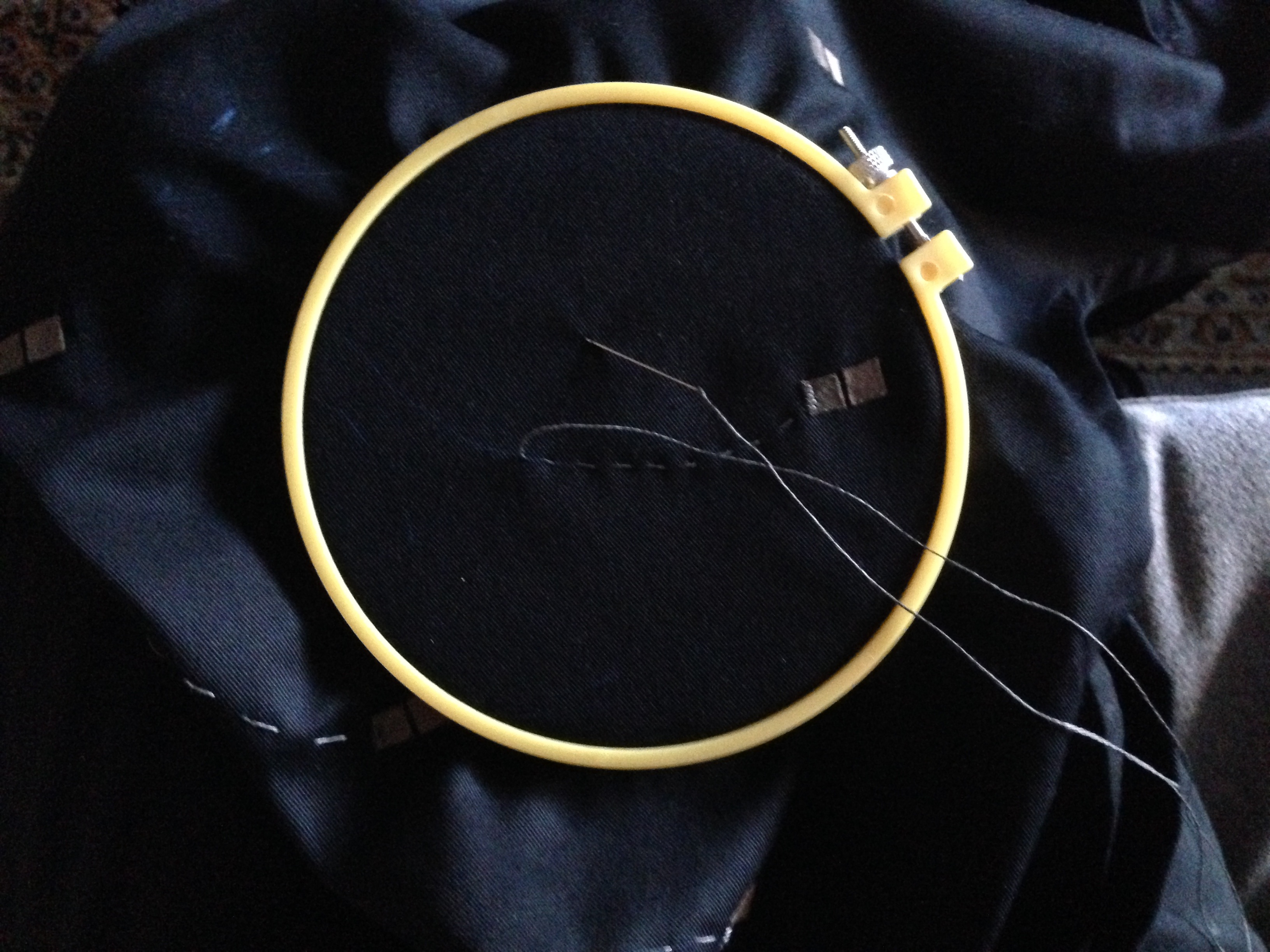
- 2) Conductive thread tends to knot. A lot. This will be hands down the most annoying part of the process, depending on how zen you are with your sewing technique. Because the thread is made of stainless steel fiber, the edges of the fiber are much more likely to attract and stick to one another, causing a massive pile up right outside your most recent stitch. I highly recommend using an embroidery hoop. It is worth the time to move it along. Watch as you pull the string through and keep your hand on the back of the stitch. This will let you unravel a know before it becomes a huge problem.
- 3) Higher resistance. Depending on the type of thread you use and how exacting you are with another stitch that folds in on itself, the longer the thread to connect two components, the higher the resistance. This means that not all the current is getting from your power source to the component. Here that means dimmer LEDs. Since our the Forward Voltage on our LEDs is 3.0-3.2 V and each pin on the Flora outputs 3.3 V , we do not want increased resistance. (BUT if we were testing on an Arduino Uno, then we would want to add a 220 ohm resistor to be safe.)
Step 6: Sewing Traces, Part 2: Make the connection
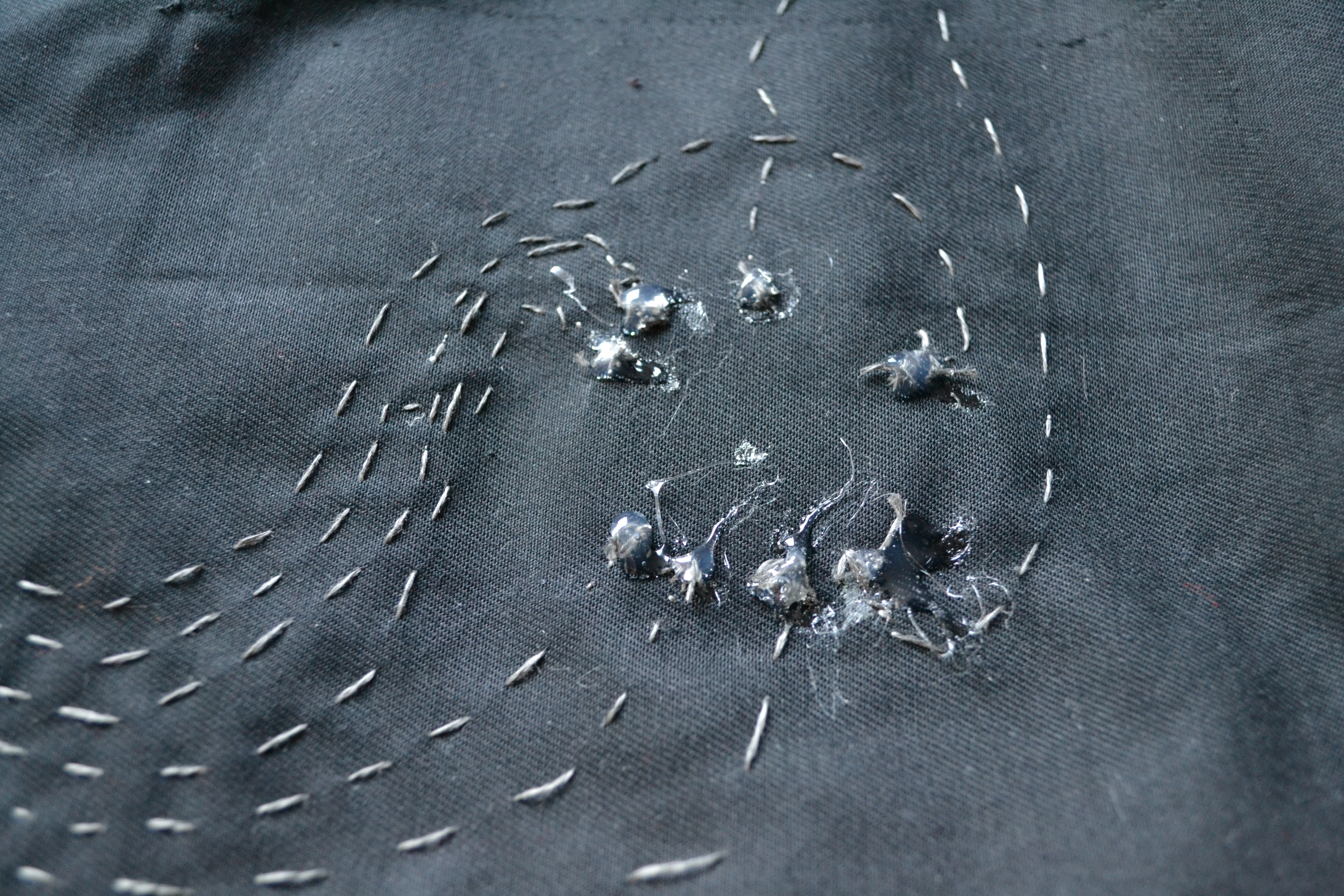
If something doesn’t work later, I can almost guarantee it is because there is a loose connection. Your traces connect the LED pads to the Flora pads. Therefore you want to be *sure* that your conductive thread is making a strong connection to the fabric. Make multiple stitches into the conductive fabric of the LED pad before shooting off for the Flora. We will reinforce these later with hot glue, but still one or two won’t cut it in the long run.
Once you are done here, begin making straight stitches. Try to keep your stitches to a quarter inch long; this will prevent them from snagging or touching other traces later. You can stick to one side of the fabric by picking up a second stitch. Depending on your design, you may have to jump over some traces to prevent them from touching. Check out the finished version:

The same goes for connecting the Flora. The pads aren’t totally necessary, just one solution to decreasing the chance of a lose connection by increasing surface area. By the end, I found that making one stitch on each of the outside edges of the pad (so it looks like an upside-down “v”), then filling in the “v” with more stitches creates a strong connection.

Step 7: Knotting off
Once you have finished sewing a trace, knot it off. To do this:
1) Make sure you are on the back
2) Sew a small stitch into the back of the fabric, but don’t pull the thread all the way through.
3) When you have a small loop, thread the needle through, and pull gently until you have what looks like a slip knot. Do this one or two more times.
Secure all knots with a touch of hot glue.
Step 8: Sew on the resistors
You need to connect a 200K Ohm resistor (you can change this value depending on the sensitivity you want) from the sensor pin (A11/D12) to Ground. I wound two legs of two 100k Ohm resistors around each other, then used needle nose pliers to create a loop I could sew.
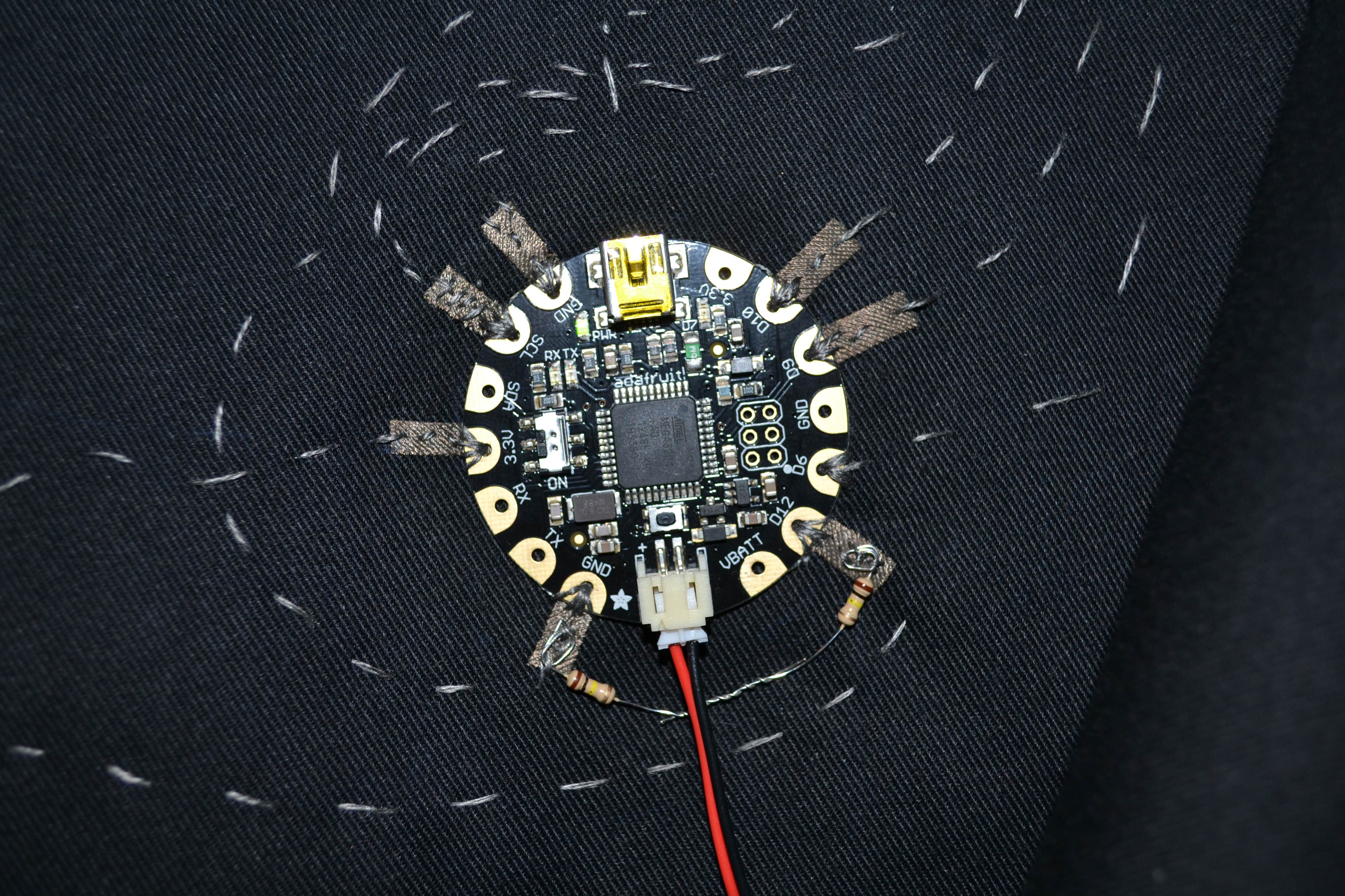
Step 9: Connect the sensors to Flora
Adhere the sensors to the fabric. Sew one to power (3.3V pin) and one to the sensor pin.

Step 10: Soldering the LEDs
Turn your soldering iron down to a lower heat and cover the tip (cringe) with a bit of solder. Using another tool (that is not your finger) hold down the LED while you solder it. Continue holding it until you see the solder turn a mat silver. Don’t worry if it is only connected in one spot. We will reinforce with hot glue in a sec. Solder the other side of the LED. Grab a multimeter and test the connection. If it’s strong, go ahead and hot glue it. If not, you may want to resolder.

Step 11: Find your threshold
Upload the code onto the Flora. Place your two fingers on the sensors and open the serial port. Take a few deep breaths or holding your breath until you see a change in values. Do this a few times to estimate an average of where your baseline is. Once you feel like you have a good number, change the float myStressThreshold variable.
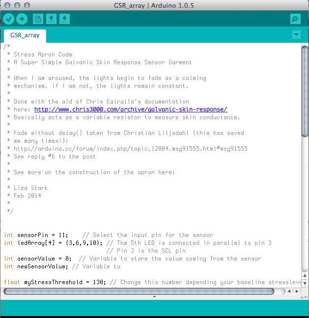
Click above to download the sketch.
Again, a caveat for some of you: This is a SUPER simple sensor that acts as a variable resistor to measure skin conductance. Hence, it won’t be completely accurate and you might have some noise. For more advanced sensors with low pass filters, check out Chris Kairalla’s documentation.
Step 12: Try it on!
