Heating Circuits for Thermochromic Inks

Thermochromic ink changes state in the presence of heat. When any heat source is applied (e.g. body heat, hair dryer, or electrical current), the pigment turns colorless. Here we will assume you want to use current to control the pigment color change.
In this overview, we’ll look at:
- Variables to consider
- Heating elements
- Circuits
- Choosing a power source
- Code
- Other resources
To see some examples in action, check out this post.
Variables to Consider
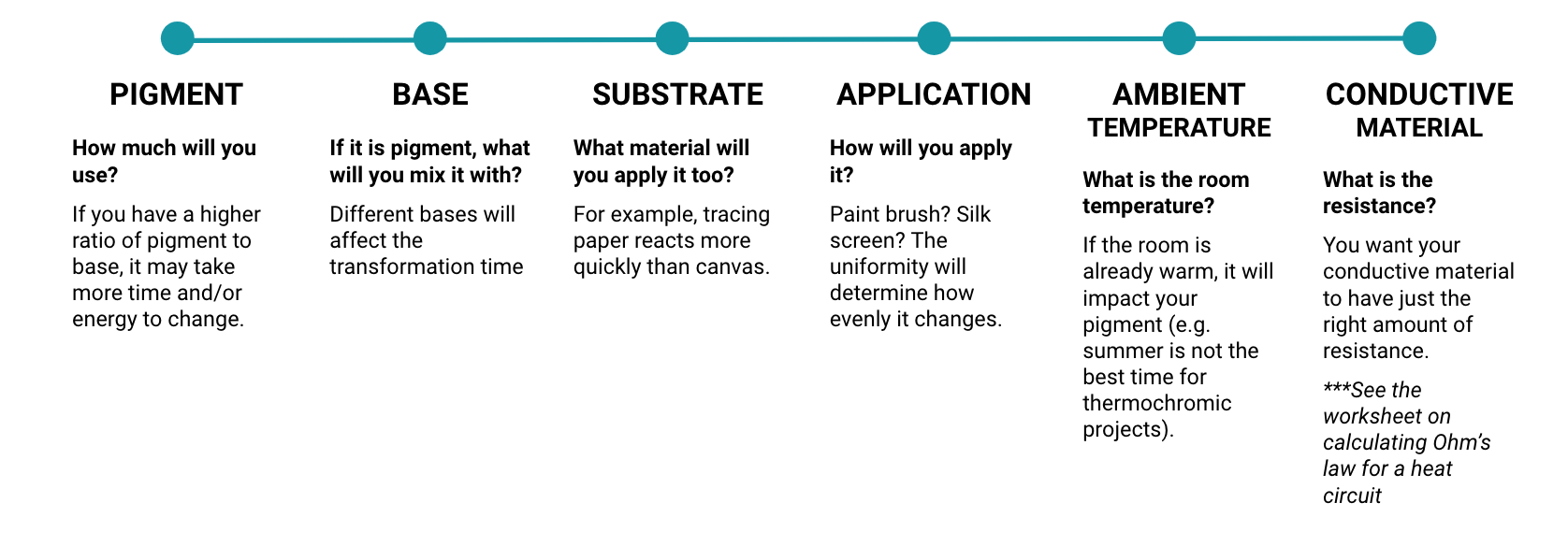
There are a few things you need to take into account when thinking about your design and implementation:
Heating Elements
Usually if we feel heat coming off of a circuit or component, it means something is wrong. For example, perhaps you have a short circuit. In this case, we actually want to generate enough heat to change the pigment. We can do that using conductive thread, nichrome wire, or flexinol. You can also use conductive fabric, but be sure to test that it actually has some resistance. Use your multimeter to check.
So, for your heating element, you want to choose a material that has a little bit of resistance and that can uniformly dissipate the heat from the circuit. Here are a few options I like:
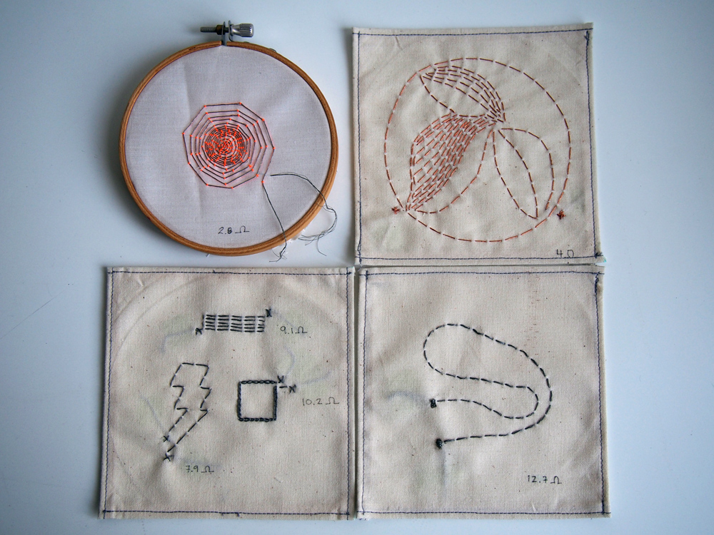
Karl Grimm silver or copper thread. This thread is very conductive, so you have to use enough to create at least 2.5 ohms of resistance.
Stainless steel conductive thread: This thread tends to have a lot of resistance, so you don’t need to use too much of it.
You should create multiple swatches of heating elements to test your design. You can find a YouTube playlists of tests I’ve made here.
Circuit
Ok. So you have your heating element. Great! Now how do you control it with Arduino?
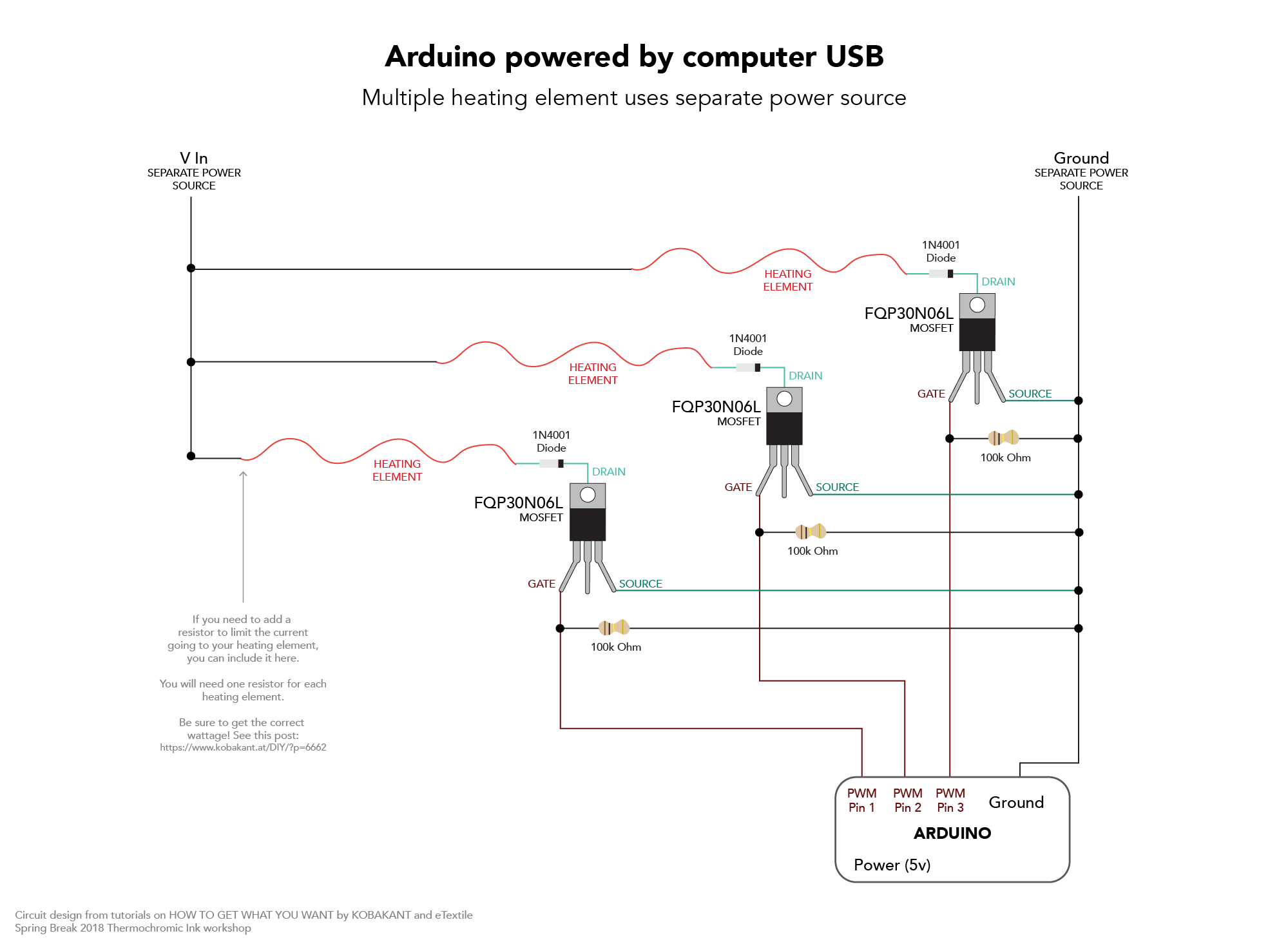
![]()
Heating takes a LOT of power – current to be specific. We want about 800mA to 1.3 Amps for this circuit. Arduino pins cannot provide the power we need to warm a heating element. Remember: you can’t draw more than 40mA from a pin.
This means we need a separate power source for the heating element using a high load circuit. We can do this using the fantastic, amazing, phenomenal transistor – a MOSFET to be specific.
Here we will use an N-channel MOSFET FQP30N06L from Sparkfun. If you’ve looked at other thermochromic tutorials, you may have seen a TIP120 or TIP122 used instead of a MOSFET. I used TIP120s for years until I helped a friend on a larger project and realized these really weren’t the most appropriate. Here’s a comparison:

Let’s take a look at how this works. Basically, we are using this transistor as an electrical switch.
By applying a small amount of voltage to the gate using the Arduino, current can flow between the drain and the source. In other words, when we digitalWrite a pin HIGH or analogWrite a value to a pin, we turn on the secondary power source to heat up the thread.
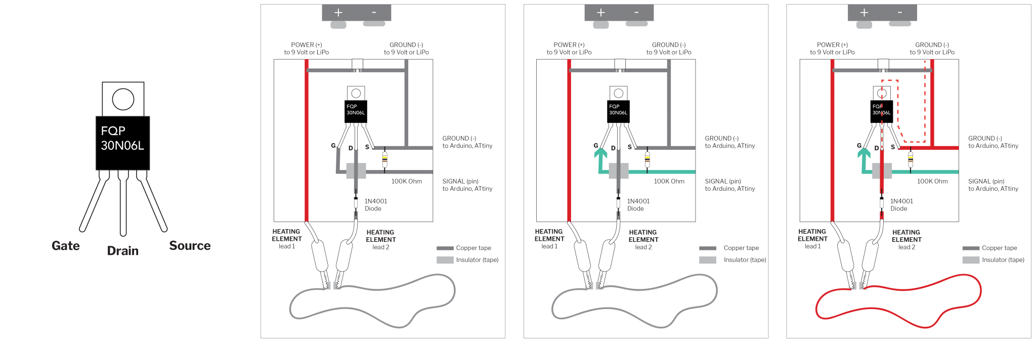
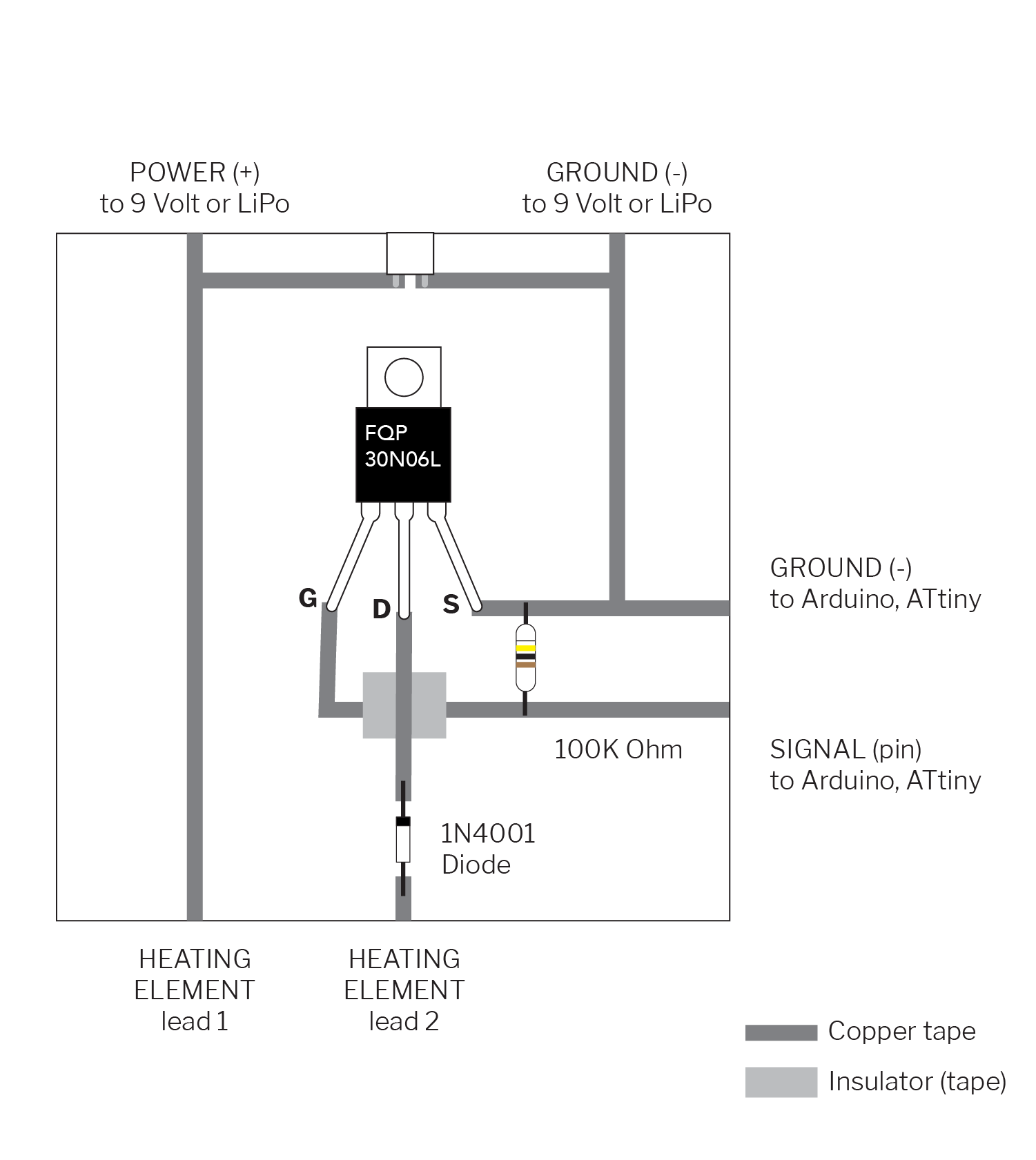
Here are a few circuit diagrams you can used according to your project:


Choosing a Power Source
Now we know how to make the circuit, let’s talk about how to power your circuit. For wearable projects, you will probably want to use a battery. For stationary projects, you can use a wall power source.
-

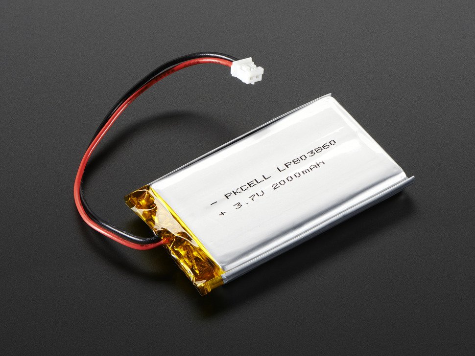
- LiPo Battery 3.7 volts
-
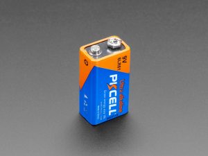
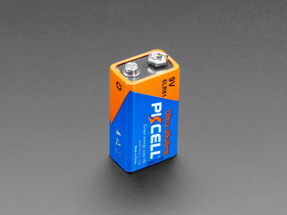
- 9 volt battery
-
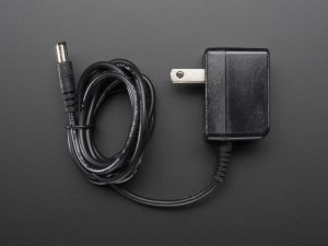
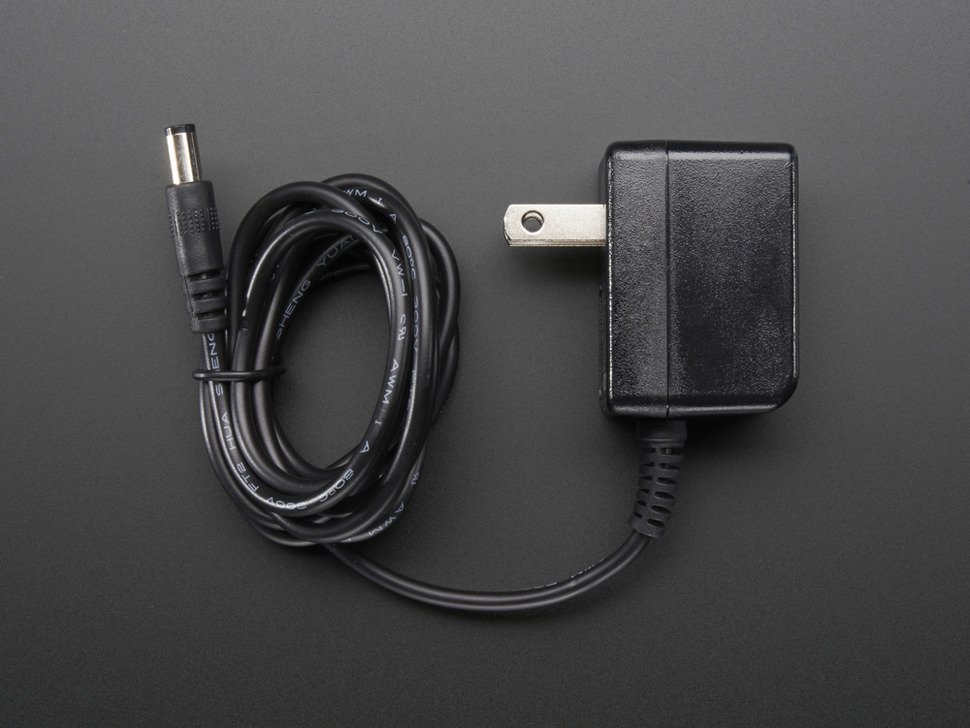
- Wall power supply
- Lipo Batteries are 3.7 volts and come in different milliamps per hour sizes (higher will last longer). Here’s a good tutorial on them from Adafruit.
- 9 volt batteries give as much current as needed.
- Wall power sources come in different voltages and amperages. For example, Adafruit has a 5V DC 2A power adapter, 9V DC 1A power adapter, 12V DC 1A power adapter, etc. If you use this, be sure that the wall source is regulated – don’t just plug in any old one you have. Here’s a good tutorial from Adafruit.
- Here are some other options for power as well.
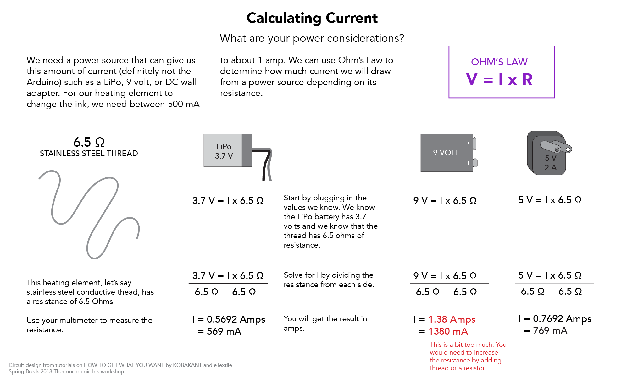
But how do you know which one to choose? You can use Ohm’s Law to figure it out what voltage is appropriate: V = I x R. We can determine the resistance of our heating element using a multimeter and we know we want to have anywhere between 800 milliamps and 1.3 amps. So now we just need to solve for the voltage. Check out the worksheets below for a few examples.

Code
As I mentioned above, you use the Arduino to control the amount of power flowing from the second source. Basically, all you have to do it write a value to the pin attached to the heating element. The trick is that you don’t want too much current running through the circuit all the time as it would get too hot. To avoid this, we switch between an on and off state using digitalWrite or analogWrite:
-
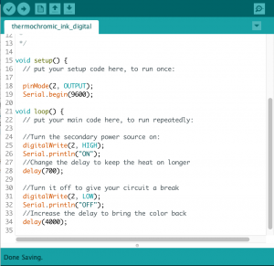
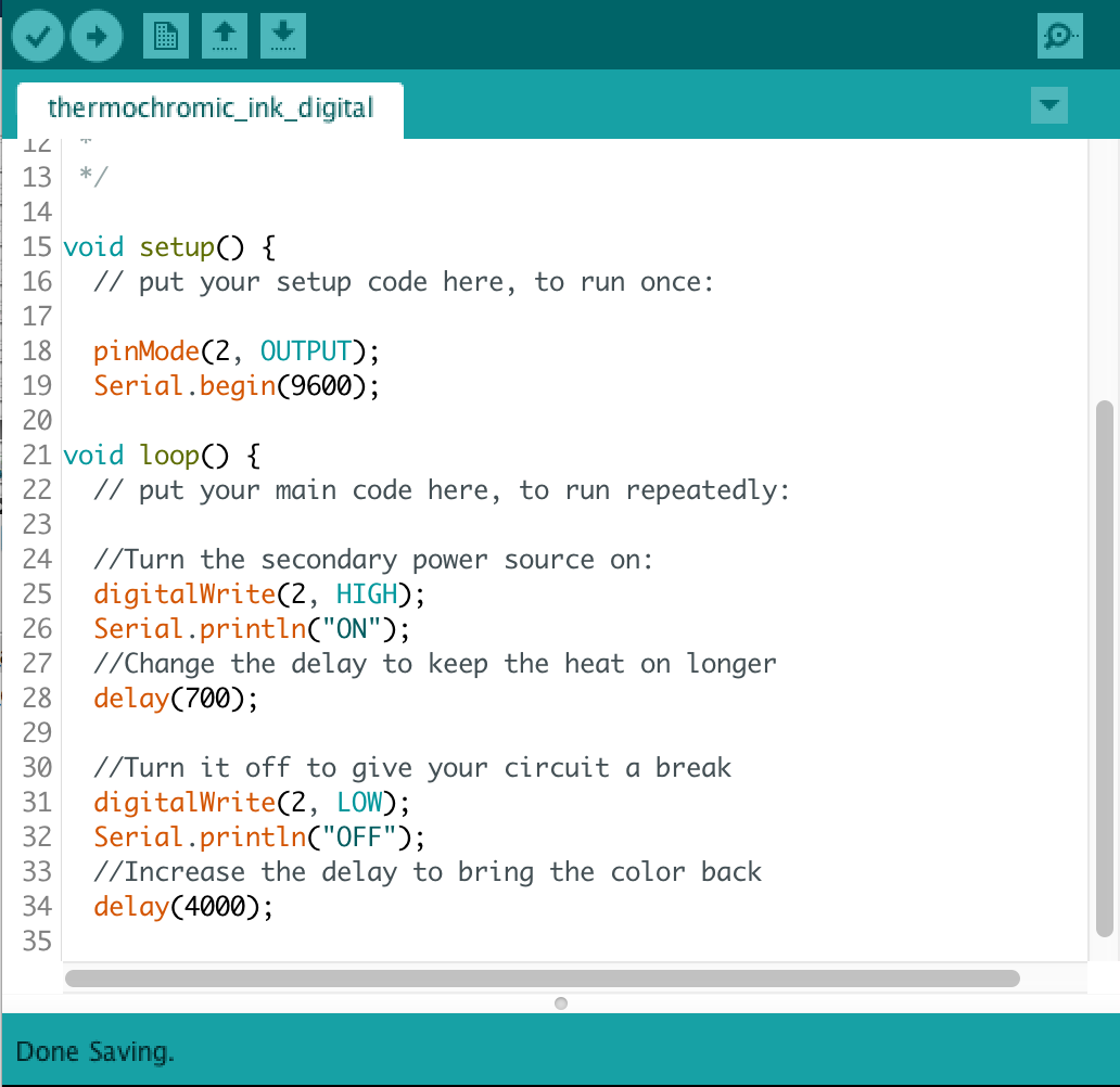
- Using digitalWrite()
-

- Using analogWrite()
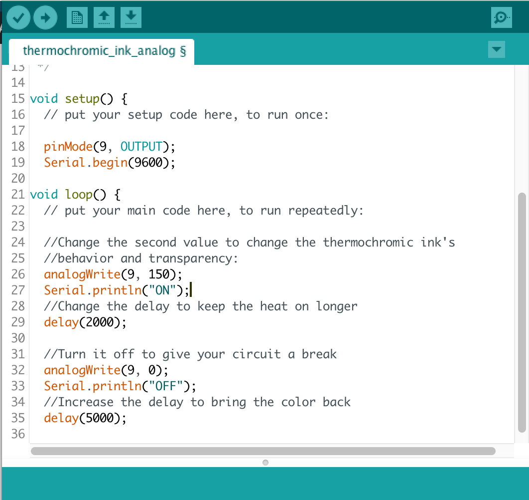
I prefer to use analogWrite because I can have more control over how much current I am letting through. If I am not letting as much through, I am comfortable keeping it on for longer with a shorter delay. Depending on what you are trying to accomplish, try changing the delay() values to change the behavior. Here is a link to the code.
Other Resources
MATERIALS
Kobakant’s material list
Sparkfun
SFXC
ELECTRONICS
TIP vs Mosfet– overview of specific differences from Arduino forums.
Building a Heat Controlling Circuit from eTextile Summer Camp
Heat Controlling Circuit by Kobakant
ITP High Current Loads
High-Power Control: Arduino + N-Channel MOSFET
FQP30N06L Datasheet
EXAMPLE PROJECTS + TUTORIALS
In All Different Colors, Workshop by Kobakant
FabTextiles
Warming Up, Instructable by Beam
HairIO
Designing Dynamic Textile Patterns by Linda Worbin, Thesis for Swedish School of Textiles